Pulse and Square Wave Generator
The square wave is a special type of pulse In digital circuits, pulses can make the voltage either more positive or more negative. Usually, ...
The square wave is a special type of pulse
In digital circuits, pulses can make the voltage either more positive or more negative. Usually, the more positive voltage is called the high state and the more negative voltage is called the low state. The length of time between the rise and the decay of a single pulse is called the pulse duration or pulse width. Multiple pulses often occur in a sequence called a pulse train, where the length of time from the beginning of one pulse to the beginning of the next is called the pulse interval.
Digital pulses usually have well-defined shapes (voltage-vs.-time graphs, as might be observed on an oscilloscope ) such as rectangular or triangular. In nature, however, pulses can have irregular shapes and can occur at random intervals. A good example is an EMP (electromagnetic pulse) generated by a lightning discharge in a thunderstorm, a solar flare, or a transient "voltage spike" that can occasionally occur on a utility power line.
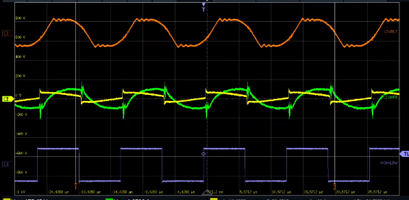
Impulse and square wave graph:
Simple square wave generator
Typically square wave generators are based on symmetrical multivibrator with bipolar transistors of the same structure and with two frequency determining network. However, you can construct more simple oscillator with two transistors of different structure (see figure 1) with only one frequency determining network.
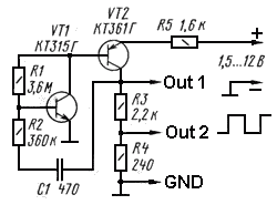 |
| Square wave generator circuit diagram - C1 - 470 pF, VT1 - BC547, VT2 - BC557 |
The circuit works this way: when the supply voltage is applied (capacitor C1 is not charged) the transistor VT1 begins to conduct the current flowing through the bias resistor R1. Collector current of this transistor is the base current for the transistor VT2 and this collector current opens the transistor VT2. The voltage at the collector load of the transistor VT2 increases through a network of C1R2, and this further opens the transistor VT1, and as a result there is an avalanche process of opening the two transistors - it's forming the front of the rectangular pulse.
The duration of the pulse is determined by charging the capacitor C1 through resistor R2. As the capacitor C1 is charging, the base current of the transistor VT1 is reduced, and there comes a time when there is starting an avalanche process of closing both transistors. On the load is formed a falling pulse edge. The duration between pulses is determined by the duration of the discharge of the capacitor C1 by the current flowing through resistors R1 and R2. Then the process repeats.
The work of the generator can be explained differently. Two-stage amplifier circuit has a positive feedback (network R2C1) and in the same time the amplifier is put in the linear mode of the transistor VT1 by applying bias on its base through resistor R1. Therefore, the relaxation oscillations are generated. To stabilize the operation of the generator each cascade has a negative feedback - it is weak in the first stage (resistor R1), and in the second stage the emitter circuit of transistor VT2 has a resistor R5.
Use pulse input to MOSFET gate for resonant circuit to generate free energy
✰* Revealed At Last: Ancient Invention Generates Energy-On-Demand
The design includes:
- Harnessing electricity from the Earth: Neither is Schumann Resonance, nor is it known by Electromagnetism. It's The Sea of Energy in Which the Earth Floats
- Extracted from ordinary electricity by the method called “fractionation.”
- Reverse Tesla coil - "Back to Back" mechanism
- Combination of radiant energy and negative resistance to amplify electricity
- And many other plans for Free Energy.
Note: Square pulses belong to the group of fundamental pulses in electronics. In addition to the square pulse, there are also sawtooth (triangle), trapezoidal, etc. So a machine that generates different types of pulses is needed for electronic design work.
Digital Pulse generator - Generators of various basic pulses
Simple bench pulse generators usually allow control of the pulse repetition rate (frequency), pulse width, delay with respect to an internal or external trigger and the high- and low-voltage levels of the pulses. More-sophisticated pulse generators may allow control over the rise time and fall time of the pulses. Pulse generators are available for generating output pulses having widths (duration) ranging from minutes down to under 1 picosecond. Pulse generators are generally voltage sources, with true current pulse generators being available only from a few suppliers. Pulse generators may use digital techniques, analog techniques, or a combination of both techniques to form the output pulses. For example, the pulse repetition rate and duration may be digitally controlled but the pulse amplitude and rise and fall times may be determined by analog circuitry in the output stage of the pulse generator. With correct adjustment, pulse generators can also produce a 50% duty cycle square wave. Pulse generators are generally single-channel providing one frequency, delay, width and output.
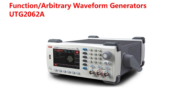
1. UNI-T UTG932 UTG962 Function Arbitrary Waveform Generator Signal Source Dual Channel 200MS/s 14bits Frequency Meter 30Mhz 60Mhz
Output Waveforms: Sine,square, pulse, ramp, noise, DC ,arbitrary
Output frequency range:1uHz-30MHz/60MHz
High accuracy, broad band 6 bit frequency ,counter,range:100mHz-100MHz
Two equivalent-performance channels
4.3 inches TFT LCD
Multi-language menu ,easy to operation
More details: Function Arbitrary Waveform Generator Signal Source Dual Channel
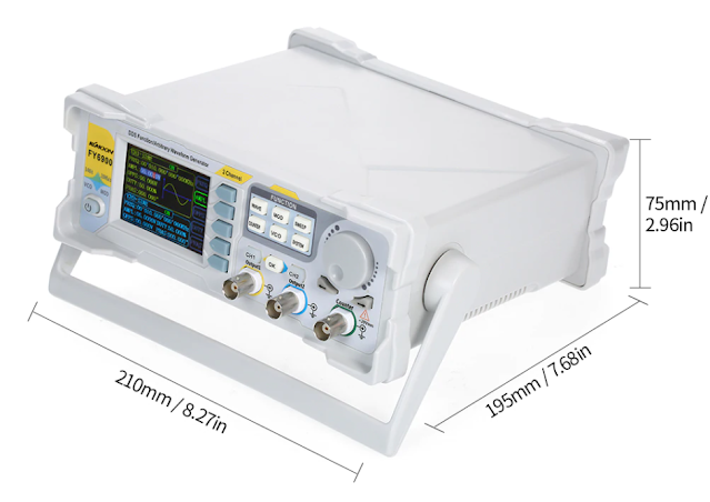
2. KKMOON 20/60/100MHz Module Digital DDS Signal Generator Waveform Generator Pulse Signal Source 250MSa/s Frequency Meter
Adopt the Direct Digital Synthesizer (DDS) technology and provide stable, precise, pure and low distortion signals.
2.4 inch TFT color LCD with 320*240 resolution, simultaneously display parameters and graphics of CH1 and CH2.
Adopt MagicPulse Technology, Low Jitter(RMS)<200ps.
The instrument uses 14-bit high-speed D/A converter chip (5Vpp output quantization error is less than 1mV), 300MSa/s sample rate, 14bits vertical resolution.
Can output up to 99 groups of functions / arbitrary waveform, contains 35 groups of preset waveforms and 64 groups of user-defined waveforms. Preset waveforms: Sine, Square (Duty Cycle adjustable), Pulse (Pulse width and cycle time can be set accurately), Triangle/Ramp, CMOS(0~12V), Four channels TTL, Exponential Rise, Exponential Fall, Noise, ECG, DC etc.
Enable to store 64 arbitrary waveform data files, each one of waveform storage depth 8192 points * 14bits; (The longer the waveform storage depth, the more detail the waveform is saved, and the signal details can be restored with high precision.)
Various modulation types: AM, FM, PM, ASK, FSK and PSK modulations.
More details: KKMOON 20/60/100MHz Module Digital DDS Signal Generator Waveform Generator Pulse
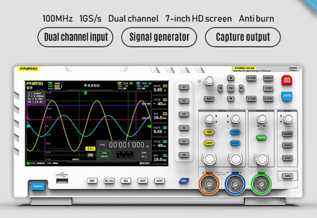
3. FNIRSI 1014D 7Inch TFT LCD Display Screen Portable Digital Oscilloscope 2 In 1 Dual Channel Input Signal Generator 100MHz
FNIRSI 1014D 7Inch TFT LCD Display Screen Portable Digital Oscilloscope 2 In 1 Dual Channel Input Signal Generator 100MHz* 2 Ana-log Bandwidth 1GSa/s Sampling Rate 1GB Storage
FNIRSI-1014D is a two in one oscilloscope and signal generator, the real-time sampling rate is 1GSa / s and with 100MHz* 2 ana-log bandwidth, with 7inch TFT LCD display screen, the built-in high-voltage pro-tection module can tolerate up to 400V continuous voltage, without worrying about the oscilloscope burning accident caused by the probe not moving to 10x gear, built in DDS function signal generator and the industry's ori-ginal chopping output (@ 2.5vpp), all signal frequency step is 1Hz, support 14 kinds of standard function signal and a customizable chopping signal, chopping The output device intercepts part or the whole part of the complex signals measured by the oscilloscope as the output signal of the signal generator, which can store up to 1000 customized cut-off signals. Come on and try it, it will not let you down.
More details: Display Screen Portable Digital Oscilloscope 2 In 1 Dual Channel Input Signal Generator 100MHz
